Table of Contents
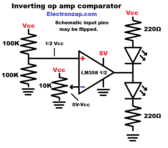
Comparators take signal voltage, and compare it to a reference voltage. The output goes high when + get a higher voltage than -. Whereas the output goes low, when + get a lower voltage than -.
Digital inverters output a voltage that is more like the reference voltage than the signal voltage.
Reference voltage is assigned to the non inverting (+) input. This is typically a fixed voltage, that you want to compare a signal to.
Signal voltage is applied to the inverting (-) input. This voltage can come from any source that you want to monitor in order to compare to the reference voltage.
- – input voltage higher than + voltage = a low output.
- – input voltage lower than + voltage = a high output.
The 358 op amp is a single supply output integrated circuit (IC)
- Low output = 0V. The 358 IC output connects pretty well to ground internally.
- High output = approx. 1.5V less than the positive supply (Vcc).
Brief Circuit Schematics with Short Video List of Pages
Assorted integrated circuits (ICs) kit. Included is the LM358, NE555 timers and other commonly known ICs. I have previously covered some of the other ICs in YouTube videos. It is an Affiliate link ad that supports this channel.
Video:
To support this site, check out the following links:
- Become a Patron!
- Check out my YouTube videos! https://www.youtube.com/c/Electronzap/videos
- Products I used in my videos or otherwise think look like a good buy. As an Amazon associate, I earn from qualifying purchases. https://www.amazon.com/shop/electronzapdotcom
- Information on this site is not guaranteed to be accurate. Always consult the manufacturer info/datasheet of parts you use. Research the proper safety precautions for everything you do.
- Electronzap is a participant in the Amazon Services LLC Associates Program, an affiliate advertising program designed to provide a means for sites to earn advertising fees by advertising and linking to amazon.com.