Table of Contents
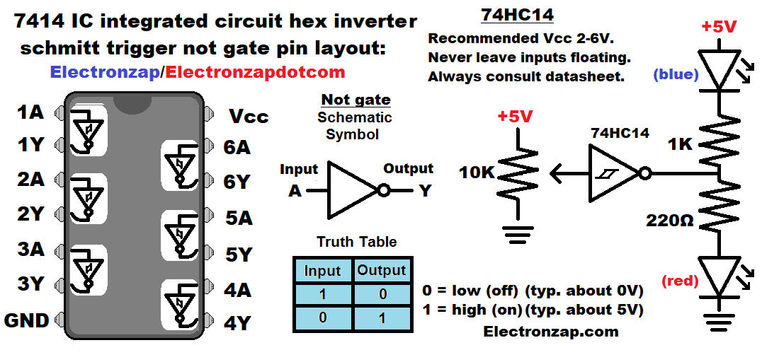
- Hex: 6 (logic gates in this case)
- NOT logic gate: Output is the inverse of the input. If the input signal is high, then the output is low. Whereas, if the input signal is low, then the output is high.
- High is often close to 5V. Also commonly called a 1. May indicate that something is on.
- Low is usually close to 0V. Also commonly called 0. May indicate that something is off.
- Schmitt Trigger: There is a middle ground input voltage (hysteresis) where the output stays in either the high or low state in order to prevent rapid triggering back and forth. The output stays in whichever state it was last put in to until the signal exceeds the other hysteresis point.
Video:
To support this site, check out the following links:
Art of electronics is easily my favorite learning electronics book. It helps to already be familiar with basic electronics while studying it. It inspires many of my demonstration circuits. An affiliate link ad that supports this site.
- Become a Patron!
- Check out my YouTube videos! https://www.youtube.com/c/Electronzap/videos
- Products I used in my videos or otherwise think look like a good buy. As an Amazon associate, I earn from qualifying purchases. https://www.amazon.com/shop/electronzapdotcom
- Information on this site is not guaranteed to be accurate. Always consult the manufacturer info/datasheet of parts you use. Research the proper safety precautions for everything you do.
- Electronzap is a participant in the Amazon Services LLC Associates Program, an affiliate advertising program designed to provide a means for sites to earn advertising fees by advertising and linking to amazon.com.