Table of Contents
Series resistances have a predictable fraction of the total voltage across them, at any terminal where they connect. That voltage probably can’t power a load though. It is not meant to have to provide much, if any current. It is generally just used as a signal, which other circuitry, or volt meters, can look at.
Equal value resistors are easy to calculate.
The signal output voltage is in relationship to ground.
- 2 Equal value resistors, with a voltage across them, will have half that voltage at the node where the 2 resistors connect.
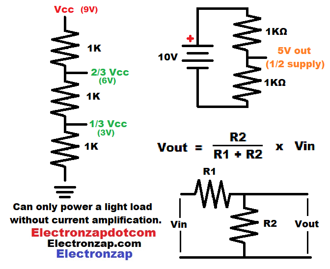
- If the supply voltage (Vcc) across them is 10V, then there will be 5V where they connect.
- If Vcc is 5V, then there will be 2.5V where the resistors connect.
- 3 equal value resistors has 2 nodes which can be used as signal outputs.
- One node has 2/3 the resistance on the low side of the power source, compared to the high side. Therefore it will output 2/3 of the supply voltage.
- With a 9V supply, the high side node will output 6V.
- The other node has 1/3 of the resistance on the low side of the power source. Therefore it will output 1/3 of the supply voltage.
- With a 9V supply, the low side node will output 3V.
- One node has 2/3 the resistance on the low side of the power source, compared to the high side. Therefore it will output 2/3 of the supply voltage.
You can calculate any voltage divider node with the formula Vout = R2/(R1+R2) x Vin
- Vout is the signal voltage.
- R1 is the resistance on the high side of the voltage divider. High side is closer to the positive power terminal.
- R2 is the resistance on the low side of the voltage divider. Low side is closer to ground, which is usually the negative terminal of a single supply DC circuit
- Vout is the signal voltage.
- Add R1+R2 together. Their resistance in Ohms.
- Take the value of R2, and divide it by the result in step one.
- Take the result in step 2, and multiply it by the total voltage across the voltage divider. Which will be the supply voltage, if the voltage divider connects to both supply terminals. That result will be your voltage divider output signal
Brief Circuit Schematics with Short Video List of Pages
Video:
To support this site, check out the following links:
- Become a Patron!
- Check out my YouTube videos! https://www.youtube.com/c/Electronzap/videos
- Products I used in my videos or otherwise think look like a good buy. As an Amazon associate, I earn from qualifying purchases. https://www.amazon.com/shop/electronzapdotcom
- Information on this site is not guaranteed to be accurate. Always consult the manufacturer info/datasheet of parts you use. Research the proper safety precautions for everything you do.
- Electronzap is a participant in the Amazon Services LLC Associates Program, an affiliate advertising program designed to provide a means for sites to earn advertising fees by advertising and linking to amazon.com.