Table of Contents
A capacitor with a parallel resistor and in series with a push button switch, will be fully charged whenever the button is pressed.
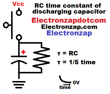
Releasing the button will rapidly discharge the capacitor through the resistor at first, but then discharge more slowly over time. Measuring the voltage with an oscilloscope shows the RC time constant voltage curve during discharge through a resistor.
One RC time constant is the time in seconds that it takes to change about 63% of the remaining voltage. Since it deals with remaining voltage, each following time constant changes the voltage less than the earlier ones did. The slope becomes flatter as it gets closer to the final voltage.
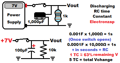
A 1,000µF (one thousand microfarad) capacitor being discharged by a 1,000Ω resistor will have an RC time constant of 0.001F x 1000Ω = 1 second.
It takes one second to discharge the first 63% of the voltage, then one second to discharge 63% of the remaining voltage, and so on.
After 5 time constants, about 99.9% of the capacitor’s starting voltage is gone. At that point it is considered fully discharged.
Video:
To support this site, check out the following links:
- Become a Patron!
- Check out my YouTube videos! https://www.youtube.com/c/Electronzap/videos
- Products I used in my videos or otherwise think look like a good buy. As an Amazon associate, I earn from qualifying purchases. https://www.amazon.com/shop/electronzapdotcom
- Information on this site is not guaranteed to be accurate. Always consult the manufacturer info/datasheet of parts you use. Research the proper safety precautions for everything you do.
- Electronzap is a participant in the Amazon Services LLC Associates Program, an affiliate advertising program designed to provide a means for sites to earn advertising fees by advertising and linking to amazon.com.