Table of Contents
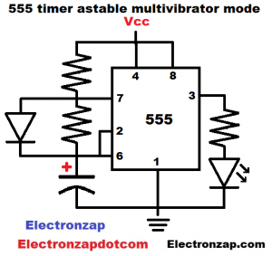
Wiring a 555 timer in astable mode results in its output alternating between high and low continuously. The timing is usually determined by 2 resistors, a capacitor, and often a diode.
- When the power is turned on, the timing capacitor starts charging through both the resistor closest to Vcc and the diode, until the capacitor reaches 2/3 of the supply voltage (Vcc).
- Output is high (LED on) while capacitor is charging.
- Once output gets to 2/3 Vcc or more, output and pin 7 both go low (connects to ground). That discharges the capacitor through the resistor parallel to the diode and the LED will be off because 0V ground is on both sides of it. There’s no voltage difference across it.
- After the capacitor voltage drops to 1/3 supply voltage or less, the output pin (3) goes high and the discharge pin (7) basically turns off. Pin 7 is an open collector pin. It’s either open (off), or it is low/connected to 0V ground. The capacitor starts charging again, just like it was doing at the top of the list.
Video:
To support this site, check out the following links:
- Become a Patron!
- Check out my YouTube videos! https://www.youtube.com/c/Electronzap/videos
- Products I used in my videos or otherwise think look like a good buy. As an Amazon associate, I earn from qualifying purchases. https://www.amazon.com/shop/electronzapdotcom
- Information on this site is not guaranteed to be accurate. Always consult the manufacturer info/datasheet of parts you use. Research the proper safety precautions for everything you do.
- Electronzap is a participant in the Amazon Services LLC Associates Program, an affiliate advertising program designed to provide a means for sites to earn advertising fees by advertising and linking to amazon.com.