Table of Contents
Light Emitting Diodes (LEDs) are simply diodes that emit light when current flows through them.
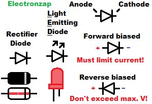
It is important that LEDs only conduct current while forward biased (Anode more positive than Cathode). I’ve found that LEDs instantly burn out once they are forced to conduct any current while reverse biased (RB). It didn’t take much more than 9 volts to get my indicator LEDs to conduct current while RB.
Current through an LED while forward biased must still be limited as LEDs don’t limit current themselves. This is commonly done with a resistor, whose value depends on the supply voltage, forward voltage of the LED, current desired, and wattage rating of the resistor.
Indicator LEDs (commonly included with learning electronics component kits) should typically have their current limited to 20mA (twenty milliamps) or less. 20mA is the same as 0.02A. Always do ohms law calculations in Amps and then convert the result to milliamps when it is between 0.001A and 1A (1,000mA and 1mA).
LEDs get brighter as more current passes through them, but burn out quicker as current goes up.
LED Anode leads (pronounce like “leeds”) typically come longer than cathode leads. The cathode side of the component also commonly has a flat edge along the rim.
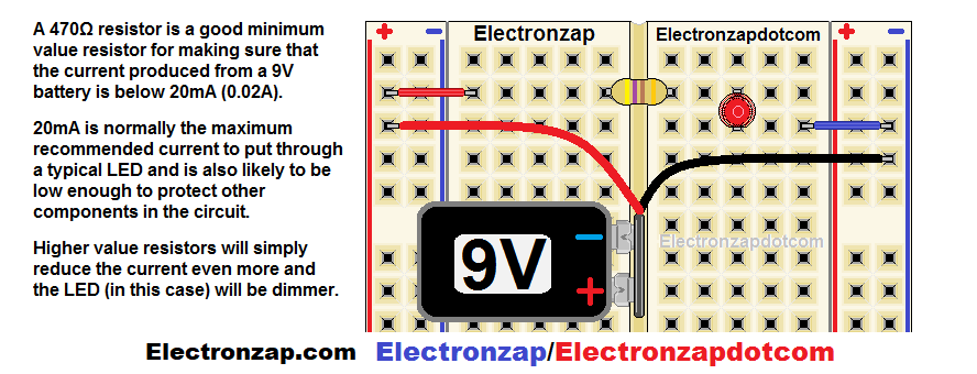
Above is one way that you may build an LED circuit on a electronics prototype breadboard. It is easy to insert the LED backwards. That is the number 1 reason why it is not lighting up if everything else looks like it is wired properly. Simply turn the LED around and it will probably light up.
Forward Voltage:
- Red, yellow, and orange indicator LEDs typically have approx. 2V forward voltage. Whereas, Blue, green, and white indicator LEDs tend to have approx. 3V forward voltage. The forward voltage is the amount of voltage that is dropped from series components while a diode is conducting while forward biased.
- An LED will start conducting a small amount of current at close to 0.4V less than it’s forward voltage.
- Indicator LED will also likely build up approx. 0.2V more than it’s forward voltage when close to 20mA of current is flowing through it.
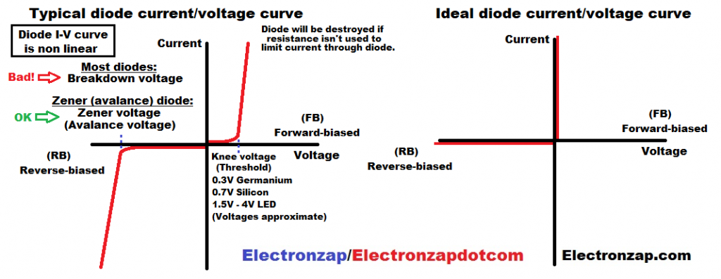
A perfect diode wouldn’t limit current at all while forward biased if any voltage is applied to it. It would also block all current while reverse biased, no matter how high the voltage gets.
Of course, a perfect diode can’t be made. But there’s circuitry out there that can behave close to a perfect diode.
Supply Voltage and current limiting resistance:
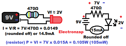
LEDs do not limit current. A common way to set the current through an LED is with a series resistor. The current at that point will be determined by the supply voltage, voltage drop (forward voltage of the LED), and the resistance of the resistor (in ohms).
- You start with the supply voltage (Vs).
- Then subtract the diode drop (LED forward voltage) from that voltage (Vs – Vdrop = Vr).
- What remains is the voltage across the resistor (Vr), which sets current (I) based on the Ohms law formula for current I = V/R. Current in amps, equals the voltage in volts, divided by resistance in ohms.
Resistor wattage:
Resistors convert electrical power (voltage times current) into heat. It is always important to try to keep the wattage (power in watts) to less than half of a component’s rated value as much as possible. Of course, you never want to exceed a component’s rated wattage value.
- Most resistors are rated for 1/4W (0.25W).
- One quarter watt (1/4W) rated resistors should have their wattage kept below 0.125W.
- Ohm/power law is usually calculated by the formula P = VI. Power (in watts) equals voltage (in Volt) across a component, times the current (in amps) through the components.
If 1/4W resistor is too low of a wattage rating for your circuit, then you might want to use…
- A higher wattage resistor.
- Two or more higher resistance resistors connected in parallel to divide the current, and thus the power.
- 2 or more lower value resistors connected in series to divide the voltage, and thus the power.