Table of Contents
Diodes have the basic electrical property of conducting current relatively easily when voltage is applied in one direction, while blocking current pretty well when voltage is applied in the other direction.
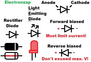
Below is a diagram that I put together a long time ago that people on Pinterest seem to like. Keep in mind that it shows the direction of electron flow, instead of using the imaginary convention current flow that is more typically used in circuit analysis.
I like the collection of diodes and Transistors in the Joe Knows Electronics Semiconductor Kit once you already have the most basic components that this kit does not include. This Ad is an affiliate link that supports this site.
Below is a important list of terminology to be aware of when studying diodes: Actual terminology and symbols used to represent them may vary a bit depending on the datasheet/source of information.
- Anode:
- Cathode:
- Forward Biased:
- Reverse Biased:
- Forward Voltage (Vf):
- Breakdown Voltage (Vb)/Avalanche:
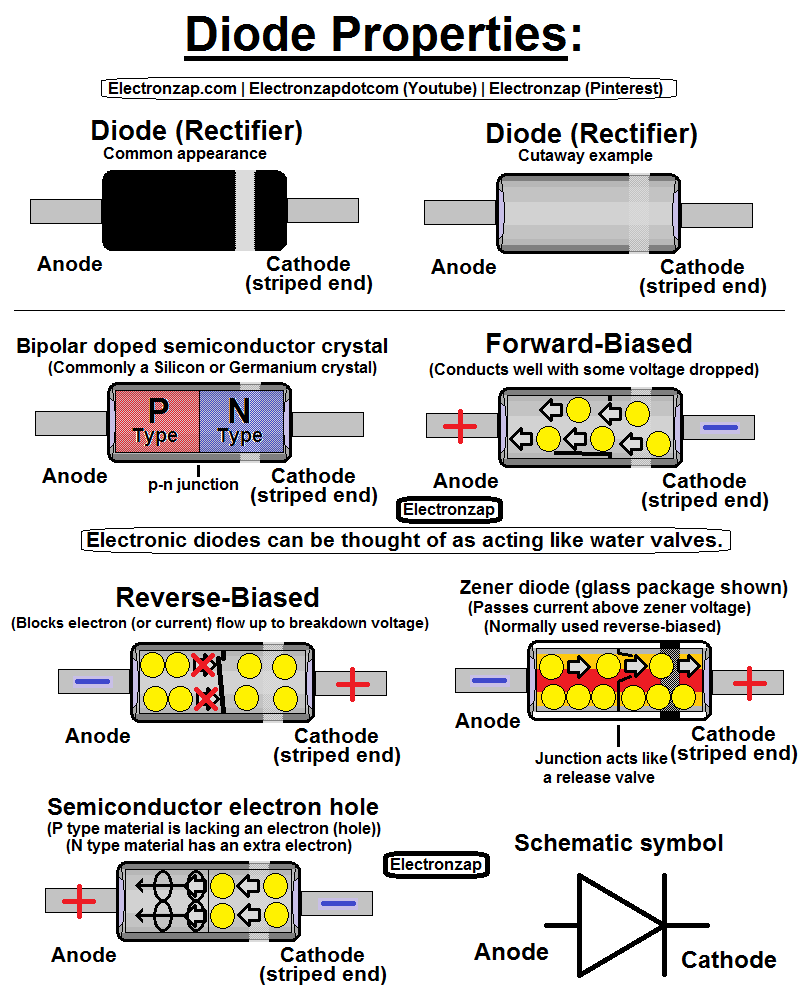
Diode: Physical appearance and schematic symbol:
Through hole (wires sticking out of both ends) diodes tend to come in cylindrical packages (appearance) with a band/stripe on one end. That band indicates the side of the diode that contains the N type material called the cathode. Most of the time through hole diodes are either black plastic with a gray band, or clear glass with a black band.
The schematic symbol for the diode is an arrow pointing towards a line/bar. The line/bar represents the cathode, and the arrow represents the Anode. The direction that the arrow is pointing (from more positive to more negative) is due to the fact that early scientists assumed that there was a positive electrical force that moved from positive to negative. Later on, electrons were discovered, but schematics were left unchanged.
Diodes that have purposes other than rectification, have slightly altered schematic symbols. The LED for example, has arrows pointing away from the symbol, because it is a diode that emits like when current flows through it forward biased.
Semiconductor material:
Pure Silicon or Germanium (crystals) are atoms with 4 valence (outer most) electrons. They are not good conductors by themselves. But their conductance can be greatly manipulated through doping.
Don’t connect a power source directly to a diode as it does not limit current. There must be other circuitry in series with the diode that limits current.
Doping for a diode is the adding of small amounts of 3 valance electron atoms to one side of the semiconductor crystal, while adding small amounts of 5 valence electrons to other side of the crystal.
The parts of the crystal that have added (doped) 3 valence electrons are called the P type material (Anode). They aren’t positively charged, but the reduced number of valence electrons located in the crystal creates “holes”.
On the other hand, the part of the crystal doped with 5 valence atoms is called N type material (Cathode). It has some extra valence electrons that can be moved relatively easily through the “holes” of the P type material.
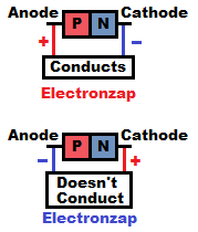
Forward biased:
Electrons flow relatively easily from N type material through P type material. This is called being forward biased. It still takes a little voltage (forward voltage) to start conducting, but any more voltage after that leads to a lot of current flow. Other circuitry is needed to limit the current based on that voltage above the forward voltage.
The forward voltage of the diode is dropped from the other series components.
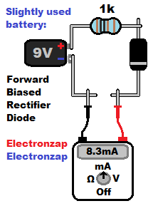
- A 1,000Ω resistor by itself, across a relatively fresh 9V battery will provide about 9mA (0.009A) of current. Also putting a meter set to measure current in series with them will display the current without changing the amount of current by a noticeable amount. Always make sure that the meter is set to measure more current than can be expected to be measured in order to avoid damaging it.
- Placing a forward biased silicon base rectifier diode in series with the resistor and relatively fresh 9V battery will provide about 8.3mA (0.0083A) of current through the circuit.
- Silicon based diodes tend to have a forward voltage (Vf) of about 0.7V. That voltage is dropped (Vd) from series components. Such as from a current limiting resistor.
- Opening the circuit and measuring it with a meter barely affects how much current flows.
Reverse biased:
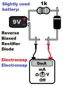
The diode greatly resists allowing electrons to flow from the P type material “holes” to the N type material. The diode is reverse biased when the Anode is more negative than the Cathode.
How well a diode blocks current/electron flow while reverse biased is one of the primary characteristics that determines what type of diode it is. The voltage that the diode is rated to block while reverse biased is usually called either the breakdown voltage, or the reverse voltage. This voltage must not be exceeded unless it is a type of diode made to conduct safely while reverse biased.
Even if the diode is specially made to break down while reverse biased, the current still needs to be limited.
Zener diodes:
Zener diodes have a zener voltage, which is the voltage that they start conducting current at while reverse biased (RB). Zeners are specially made to conduct current while RB as long as you stay below their maximum wattage rating.
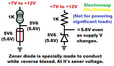
When a zener diode is conducting current while reverse biased (RB), it holds it’s zener voltage across it.
The voltage across the RB zener diode can be used as a signal voltage for other circuitry.
Often a resistor is in series with a zener diode. The zener voltage is dropped from the resistor, and the resistor sets the current from the remaining voltage difference.
Therefore, you need a bit more supply voltage than the zener voltage of the zener diode.
Keep in mind that the actual amount of current flowing through a RB zener diode will alter the actual voltage built up across it a bit.
- Higher current rises the output voltage a little bit.
- Lower current lowers the output voltage a little bit.
To support this site, check out the following links:
- Become a Patron!
- Check out my YouTube videos! https://www.youtube.com/c/Electronzap/videos
- Products I used in my videos or otherwise think look like a good buy. As an Amazon associate, I earn from qualifying purchases. https://www.amazon.com/shop/electronzapdotcom
- Information on this site is not guaranteed to be accurate. Always consult the manufacturer info/datasheet of parts you use. Research the proper safety precautions for everything you do.
- Electronzap is a participant in the Amazon Services LLC Associates Program, an affiliate advertising program designed to provide a means for sites to earn advertising fees by advertising and linking to amazon.com.