Table of Contents
If you want a diode, but you don’t want to lose a diode drop of 0.6V, or even 0.3V (Schottky diode drop), then a MOSFET might work for you.
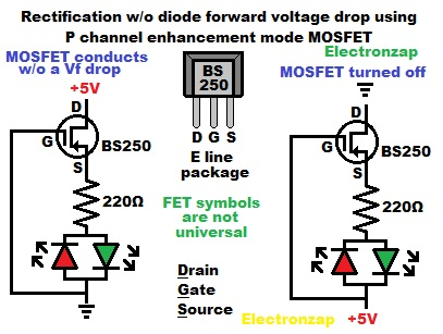
In the diagram, we have a polarity indicator circuit in series with a MOSFET.
- D = Drain
- G = Gate
- S = Source
The P channel enhancement mode MOSFET will conduct as well as it can, when there is enough negative voltage at the gate. Therefore that polarity of voltage will pass current through the MOSFET and light the forward biased green LED. Drain and Source are reversed from what you will normally see in most circuits, but that is OK for this circuit.
Switching supply polarities results in +5V being applied to the MOSFET gate which turns the P channel enhancement mode transistor off. The transistor won’t conduct, and the red RED will not light up even though it is forward biased as far as the power supply is concerned. That is because the transistor is now acting like an off switch. This is in fact, the normal way to wire a P channel enhancement mode MOSFET switch to turn it off.
Video:
To support this site, check out the following links:
- Become a Patron!
- Check out my YouTube videos! https://www.youtube.com/c/Electronzap/videos
- Products I used in my videos or otherwise think look like a good buy. As an Amazon associate, I earn from qualifying purchases. https://www.amazon.com/shop/electronzapdotcom
- Information on this site is not guaranteed to be accurate. Always consult the manufacturer info/datasheet of parts you use. Research the proper safety precautions for everything you do.
- Electronzap is a participant in the Amazon Services LLC Associates Program, an affiliate advertising program designed to provide a means for sites to earn advertising fees by advertising and linking to amazon.com.