Table of Contents
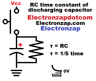
Charging a capacitor (instantly if you short circuit it, like in the diagram), and then discharging it through a resistor (by releasing the switch in the diagram) results in a quick voltage drop at first, but then a slower drop over time.
Avoid short circuiting capacitors that are larger than about 1,000µF or charged to more than 9V.
The RC time constant is calculated by taking the capacitance (in Farads) and multiplying it by the resistance (in Ohms). That gives you the time in seconds for one RC time constant. The time in seconds is often indicated by the symbol τ, which is the Greek letter tau.
- 0.001F times 1,000Ω = 1 second time constant (τ) .
- 0.001F is one microfarad (1µF). Always calculate in Farads.
One time constant (TC) is how long it will take to drop about 63% of the voltage. Another TC will change 63% of what’s left, and so on. So ultimately, it takes 5 time constants to change about 99.9% of the total voltage difference that you started with. Therefore, 5 time constants is the time that a capacitor is either considered fully charged, or fully discharged through a resistance.
Discharge RC time constant:
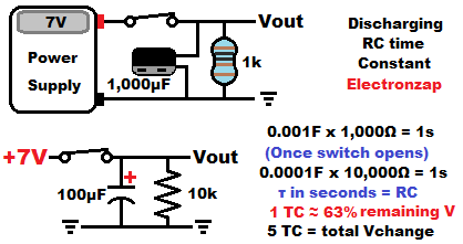
In this example, after opening the switch, it will take approx. 5 seconds to discharge the capacitor from 7V to 0V.
Video:
Charging RC time constant:
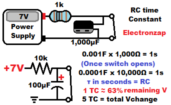
Charging a capacitor through a resistance can be demonstrated in a similar way as discharging.
First by having the capacitor discharged with a short circuit (such as a closed switch) between it’s terminals. And then opening the switch to allow the current flowing through the resistor to charge the capacitor instead of going right back to the power supply.
As the voltage of the capacitor gets closer to the supply voltage, then there is less voltage difference across the resistor. That means that there is less current flowing through the resistor, and it takes longer for the capacitor voltage to rise.
Once the capacitor voltage is the same as the supply voltage, then there’s no more voltage difference across the resistor. Therefore there is no current flow, and the capacitor stops charging. It is fully charged.
In the diagram above, it will take 5 seconds to charge the capacitor from 0V to 7V after the switch opens.
Video:
To support this site, check out the following links:
Affiliate link ad of the portable power supply used in my videos. There are larger ones that are cheaper if portability isn’t important. I primarily got this one because I can easily film it next to my circuits while making my YouTube videos.
- Become a Patron!
- Check out my YouTube videos! https://www.youtube.com/c/Electronzap/videos
- Products I used in my videos or otherwise think look like a good buy. As an Amazon associate, I earn from qualifying purchases. https://www.amazon.com/shop/electronzapdotcom
This is a new page that will be updated soon!
- Information on this site is not guaranteed to be accurate. Always consult the manufacturer info/datasheet of parts you use. Research the proper safety precautions for everything you do.
- Electronzap is a participant in the Amazon Services LLC Associates Program, an affiliate advertising program designed to provide a means for sites to earn advertising fees by advertising and linking to amazon.com.