Table of Contents
555 timer can be easily wired to make a Schmitt Trigger NOT Gate.
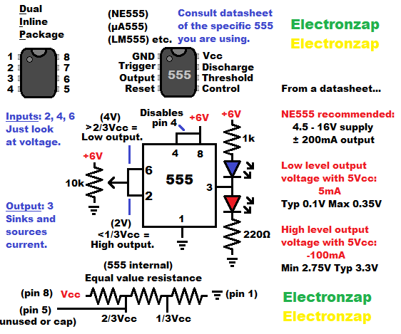
- High input signal to pin 6 (Threshold pin) results in a low output. A high input is 2/3 of the supply voltage or higher.
- Low input signal to pin 2 (Trigger pin) results in a high output. A low input is 1/3 of the supply voltage, or lower.
- Connecting pin 2 and 6 together makes sure that they both always have the same voltage signal applied to them.
- A signal applied to pins 2 and 6, which is between 1/3 and 2/3 supply, will not change the output. It must meet either the 1/3 or 2/3 supply voltage threshold needed to change state.
- Hysteresis refers to that middle ground input signal voltage where the output stays in whatever state it was last put into.
Assorted integrated circuits (ICs) kit. Included is the NE555 timers and other commonly known ICs. I have previously covered some of the other ICs in YouTube videos. It is an Affiliate link ad that supports this channel.
Video:
To support this site, check out the following links:
- Become a Patron!
- Check out my YouTube videos! https://www.youtube.com/c/Electronzap/videos
- Products I used in my videos or otherwise think look like a good buy. As an Amazon associate, I earn from qualifying purchases. https://www.amazon.com/shop/electronzapdotcom
- Information on this site is not guaranteed to be accurate. Always consult the manufacturer info/datasheet of parts you use. Research the proper safety precautions for everything you do.
- Electronzap is a participant in the Amazon Services LLC Associates Program, an affiliate advertising program designed to provide a means for sites to earn advertising fees by advertising and linking to amazon.com.