Table of Contents
The 555 timer integrated circuit makes for an easy high or low (on or off) output circuit.
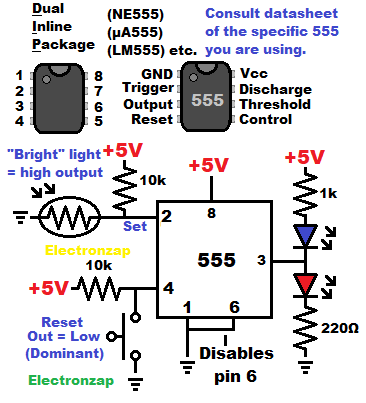
Set with light dependent resistor (LDR):
 For the demonstration circuit shown in the diagram…
- A bright enough light falling on the light dependent resistor (LDR) sets the output high.
- Pin 2 (trigger) requires a low input signal (1/3 supply voltage or less) to set the output high.
- Pressing the pushbutton switch sets the output to low if the output is high.
- Pin 4 (reset) needs an input signal close to the negative supply (low) to set the output low.
- Reset pin overpowers the trigger pin. If both of them have a low input. The reset pin will always hold the output low when it has a low input.
Brief 555 Timer Monostable One Shot Mode Circuit
Basic 555 Timer Astable Multivibrator Mode Circuits
Video:
To support this site, check out the following links:
- Become a Patron!
- Check out my YouTube videos! https://www.youtube.com/c/Electronzap/videos
- Products I used in my videos or otherwise think look like a good buy. As an Amazon associate, I earn from qualifying purchases. https://www.amazon.com/shop/electronzapdotcom
- Information on this site is not guaranteed to be accurate. Always consult the manufacturer info/datasheet of parts you use. Research the proper safety precautions for everything you do.
- Electronzap is a participant in the Amazon Services LLC Associates Program, an affiliate advertising program designed to provide a means for sites to earn advertising fees by advertising and linking to amazon.com.