Table of Contents
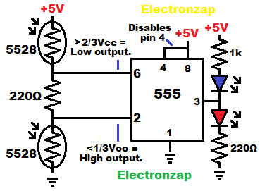
555 timers have 2 inputs that respond to 2 different voltages, even while connected together. 2 light dependent resistors (LDRs), each connected to a different supply rail, can easily set a wide range of adjustable voltages to both inputs.

With a LDR connecting an input to a supply rail, the resistance will be very low under bright light, and very high when it is dark.
That means that, when they are combined into a voltage divider, the inputs will be pulled towards the voltage of the LDR with the highest light on them.
I used a couple 5528 LDRs, to make sure they have close to the same resistance, when the same amount of light falls on them.
Kit I got my 5528, and other light dependent resistors from. An affiliate link ad that supports this site.
555 Basics:
- Trigger (pin 2) needs 1/3 or less supply voltage to set the output high.
- Threshold (pin 6) needs 2/3 or more supply voltage to set the output low.
- Between 1/3 to 2/3 supply voltage to pin 2 and 6, leaves the output in whatever state it was last put into. That is the hysteresis for this circuit.
2 LDRs Voltage Divider Basics:
2 LDRs wired as a voltage divider, each of them connected to the opposite supply rail of the other, will change voltage rapidly when light falls on them unevenly. The output voltage will be closer to the supply voltage of the LDR with the most light on it.
The following assumes both of the LDR are the same part number. I’m using 5528s in this circuit.
- Brighter high side LDR and darker low side LDR voltage divider = a higher output voltage.
- Brighter low side LDR and darker high side LDR voltage divider = a lower output voltage.
- Equal light on both of them outputs half of the supply voltage.
- I did also place a 220Ω between the LDRs and inputs.
- This is to make sure that there is always at least 220Ω of resistance protecting the LDRs if it gets bright enough that they both get close to 0Ω of resistance.
- This relatively low value (220Ω) extra resistor should not affect the output voltage much. However, higher value resistor I tested earlier definitely made it so that this circuit doesn’t work.
- The 555 inputs don’t let current in or out, and therefore don’t need to be protected from 5V.
Video:
To support this site, check out the following links:
- Become a Patron!
- Check out my YouTube videos! https://www.youtube.com/c/Electronzap/videos
- Products I used in my videos or otherwise think look like a good buy. As an Amazon associate, I earn from qualifying purchases. https://www.amazon.com/shop/electronzapdotcom
- Information on this site is not guaranteed to be accurate. Always consult the manufacturer info/datasheet of parts you use. Research the proper safety precautions for everything you do.
- Electronzap is a participant in the Amazon Services LLC Associates Program, an affiliate advertising program designed to provide a means for sites to earn advertising fees by advertising and linking to amazon.com.