Table of Contents
Astable mode 555 timers, keep alternating a high and low output. Timing is controlled by the speed of which a capacitor is being charged and discharged.
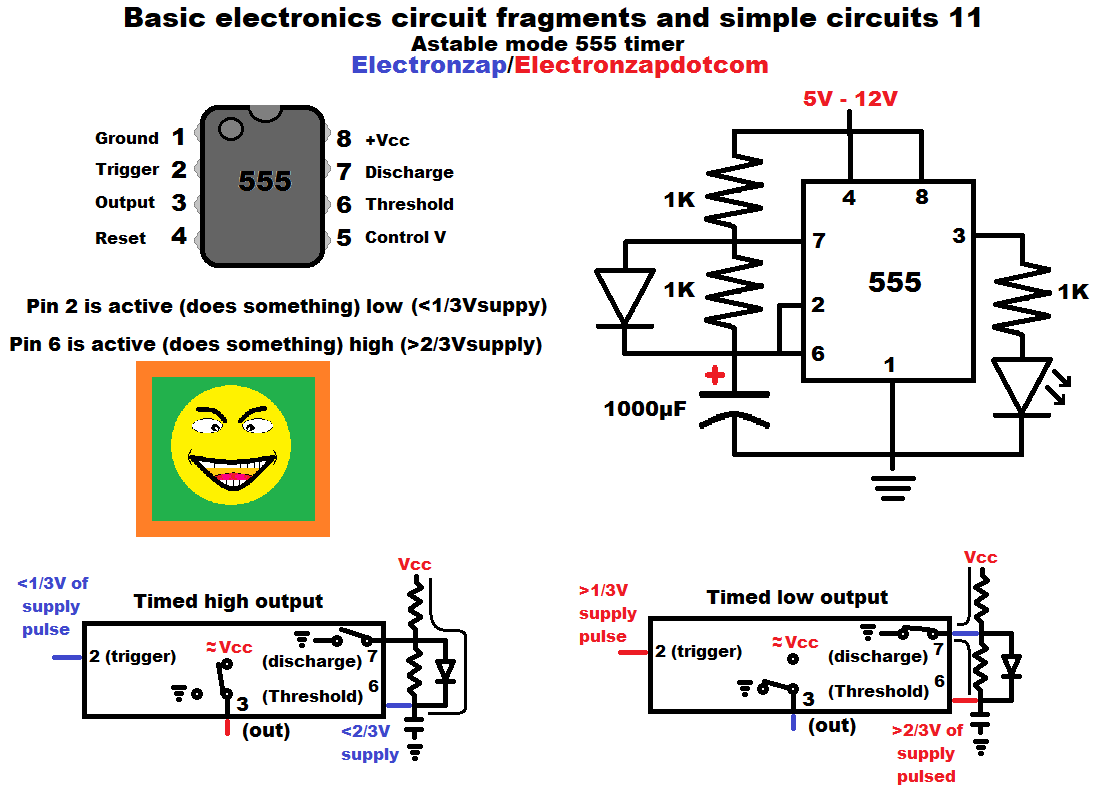
- Pin 2 and 6 monitor the voltage of the capacitor.
- Pin 6 senses when the capacitor is 2/3 or higher of supply voltage. Once so, the output goes low, and pin 7 connects to ground, discharging the capacitor.
- Pin 2 senses when the capacitor is 1/3 or less of supply voltage. Once so, the output goes high, and pin 7 basically turns off. No current flows in or out, allowing the capacitor to start charging again.
Video:
To support this site, check out the following links:
- Become a Patron!
- Check out my YouTube videos! https://www.youtube.com/c/Electronzap/videos
- Products I used in my videos or otherwise think look like a good buy. As an Amazon associate, I earn from qualifying purchases. https://www.amazon.com/shop/electronzapdotcom
- Information on this site is not guaranteed to be accurate. Always consult the manufacturer info/datasheet of parts you use. Research the proper safety precautions for everything you do.
- Electronzap is a participant in the Amazon Services LLC Associates Program, an affiliate advertising program designed to provide a means for sites to earn advertising fees by advertising and linking to amazon.com.