Table of Contents
555 Timer wired in astable mode keeps alternating a high and low output, for as long as powered is applied.
Timing is set with resistance and capacitance.
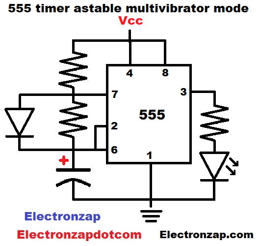
In the basic circuit shown in the diagram…
- Vcc (positive supply voltage) resistor and diode charge the capacitor up to 2/3 of the supply voltage. How long it takes depends on the resistance of the resistor, and the capacitance of the capacitor. Output is high while the capacitor is charging up to 2/3 supply voltage (Vcc).
- Discharge pin (7) is acting as an off switch while capacitor charges. It does not affect current flow at this time.
- Trigger pin (2) is waiting for the capacitor voltage to drop below 1/3 supply voltage. It is doing nothing while capacitor charges up to 2/3 Vcc.
- Threshold pin (6) is the pin that senses when the capacitor has reached 2/3 supply voltage.
- Capacitor reaching 2/3 of the supply voltage (sensed by pin 6, sets the output low, which is when it connects to ground internally. The discharge pin (7) also connects to ground at this time. The capacitor discharges through the resistor to pin 7. Pin 7 also sinks any current flowing through the resistor from Vcc.
Output low and capacitor discharge:
After the threshold pin (6) senses that the capacitor has charged to 2/3 supply voltage, the output goes low (connects to ground). The discharge pin (7) also connects to ground internally.
- Capacitor discharges through resistor between the capacitor and pin 7. The diode doesn’t conduct at this time as it is reverse biased.
- Any current flowing through Vcc to pin 7, sinks to ground through pin 7. It doesn’t affect capacitor discharge.
- Once the trigger pin (2) senses that the capacitor has discharged to 1/3 Vcc, the 555 timer sets the output high (as close to 5 volts as it can get), and turns pin 7 off. The capacitor starts charging again.
The high/low cycle just keeps repeating.
Video:
More circuit details:
- High output, means the voltage is as close to the supply voltage (Vcc) as the output can provide. Usually about 1.5V less than the supply voltage. Some voltage is loss due to the transistors used in the internal circuitry.
- Low output means that the output voltage is as close to ground as the output can provide. Typically, pretty close to being a direct connection to ground. Ground is typically considered as being 0V.
- Removing the diode will mean that the capacitor charges through two resistors, and discharges through 1 resistor. It will take longer to charge in that case, but will discharge in the same amount of time.
To support this site, check out the following links:
- Check out my YouTube videos! https://www.youtube.com/c/Electronzap/videos
- Products I used in my videos or otherwise think look like a good buy. As an Amazon associate, I earn from qualifying purchases. https://www.amazon.com/shop/electronzapdotcom
- Information on this site is not guaranteed to be accurate. Always consult the manufacturer info/datasheet of parts you use. Research the proper safety precautions for everything you do.
- Electronzap is a participant in the Amazon Services LLC Associates Program, an affiliate advertising program designed to provide a means for sites to earn advertising fees by advertising and linking to amazon.com.