Table of Contents
Single supply op amps, like the L358, have an output that can reach the negative supply voltage, but not the positive supply voltage. That makes them good for single supply (negative terminal of power source is 0V ground) voltage sources.
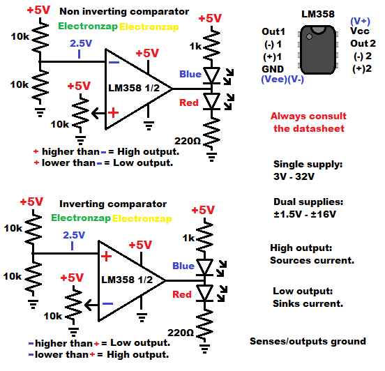
Comparator Circuits: Inverting and Non Inverting.
You can also use single supply op amps in dual supply circuits. That’s when you have 0V ground half way between a positive and negative voltage. Dual supply circuits often stay away from both + and – voltage extremes.
Assorted integrated circuits (ICs) kit. Included is the LM358 op amps and other commonly known ICs. I have previously covered some of the other ICs in YouTube videos. It is an Affiliate link ad that supports this channel.
Diagram shown above, and the video below, shows a couple LM358 comparator circuits. They also show the pin layout of the LM358 integrated circuit component, and some of it’s electrical limitations. Always consult the datasheet though for the most accurate information.
- A comparator circuit has 2 inputs and an output.
- The output either goes as close to the positive supply voltage (high) as it can, or it gets as close to the negative supply voltage (low) as it can. The LM358 can get close to the negative supply at low current while low, but falls about a volt short from the positive supply when high.
- The op amp compares the voltage at the + (non inverting) input, and the – (inverting input).
- The inputs just look at the voltage applied to them. They don’t let current through them, other than a very small amount of leakage.
- Non inverting comparator circuit has the changing signal voltage connected to the + input. While the reference voltage (usually fixed in one way or another) is connected to the – input.
- Inverting comparator circuit has the changing signal voltage connected to the – input. While the reference voltage (usually fixed in one way or another) is connected to the + input.
- High output occurs when + input has a higher voltage than the – input.
- Low output occurs when + input has a lower voltage than the – input.
Video:
To support this site, check out the following links:
- Become a Patron!
- Check out my YouTube videos! https://www.youtube.com/c/Electronzap/videos
- Products I used in my videos or otherwise think look like a good buy. As an Amazon associate, I earn from qualifying purchases. https://www.amazon.com/shop/electronzapdotcom
This is a new page that will be updated soon!
- Information on this site is not guaranteed to be accurate. Always consult the manufacturer info/datasheet of parts you use. Research the proper safety precautions for everything you do.
- Electronzap is a participant in the Amazon Services LLC Associates Program, an affiliate advertising program designed to provide a means for sites to earn advertising fees by advertising and linking to amazon.com.