Table of Contents
Light Emitting Diode (LED) circuits are simple, but teach you a lot about electronics.
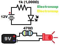
Three components make up the simplest practical circuit:
- Power source (supply):
- 12V (twelve volt) battery symbol shown the the schematic diagram.
- 9V battery drawn in the pictorial diagram.
- Resistor: Whose minimum resistance depends on the supply voltage, LED forward voltage drop and current limit, and the wattage rating of the resistor.
- A 1,000 ohm (1,000Ω or 1k) 1/4 watt resistor is good for protecting a 20mA max. LED from 12V.
- A 470 ohm 1/4 watt resistor is good for protecting a 20mA max. LED from 9V.
- LED.
- Indicator LEDs are the best type of LED to start learning electronics with.
- Their light can easily be seen with enough current through them. However, they will not light up other things very much. Too much current will reduce their life and/or destroy them.
- Low priced.
- Typically have a maximum recommended current of 20mA. 20mA is the same as 0.02A. Do calculations in Amps and then convert the result into milliAmps.
- Indicator LEDs are the best type of LED to start learning electronics with.
Indicator LED:
Being a diode (light emitting diode), an LED has the basic electrical properties of a diode.
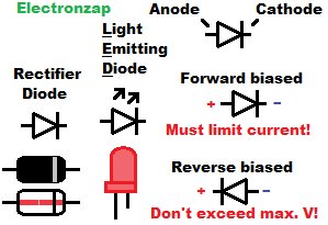
- Polarity:
- Anode needs to be more positive than cathode in order to pass current and light up. That condition is referred to as being “forward biased”.
- Indicator LEDs typically come with a longer lead (pronounced like “leed”) for the Anode, and a shorter lead for the Cathode. Sometimes there is also a flat spot along the LED rim to indicate the Cathode side of the LED.
- Anode needs to be more positive than cathode in order to pass current and light up. That condition is referred to as being “forward biased”.
- Forward voltage:
- Even while forward biased, a diode needs a certain amount of voltage to start conducting. That voltage is also dropped from series components.
- Red/Yellow/Orange indicator LEDs can be expected to have approx. 2Vf (forward voltage of 2V).
- Blue/Green/White indicator LEDs can be expected to have approx. 3Vf (forward voltage of 3V).
- Indicator LEDs typically start producing a small amount of light at approx. 0.5V below their Vf.
- Even while forward biased, a diode needs a certain amount of voltage to start conducting. That voltage is also dropped from series components.
- Forward current:
- 20mA (twenty milliamps) is the maximum current that should flow through most indicator LEDs. The current can be lower, the LED just won’t be as bright, but will last longer and save power. In most circuits, 10mA will probably be plenty of current. Some colors are brighter than others at the same current.
- Current should only flow through an LED while it is forward biased. Reverse biased current will destroy the LED. Diodes need to be specially made to be able to safely pass current while reverse biased, such as zener diodes.
Protective resistor:
The biggest decision you have to make while designing many circuits, is what resistor(s) to use. For a simple LED circuit, you have 2 primary concerns.
- Current is limited enough to protect the LED.
- In series circuits, the same amount of current flows through each component.
- Resistors set the current (I) using Ohms law I = V/R. Based on the supply voltage, minus the LED forward voltage drop, being the voltage across the resistor.
- Resistor wattage shouldn’t exceed more than half of it’s maximum wattage rating.
- Most resistors are rated for a maximum of 1/4W (0.25W).
- Wattage is calculated with the power formula P = VI (Power in watts is the voltage in volts across a components, times the current in amps through a component). Remember to convert milliAmps (mA) into amps before doing calculations.
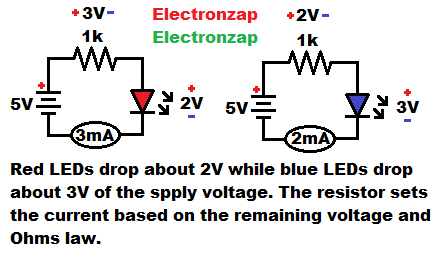
For the 2 examples in the diagram above, which show a 5V supply and 1,000Ω resistor protecting an LED:
- Red LED probably drops around 2V (it’s forward voltage).
- 5Vsupply – 2Vdrop = 3V across the resistor
- 3V/1,000Ω = 0.003A of current through the resistor, and through the LED. The current is provided by the power supply. Therefore that same amount of current flows through the power supply. 0.003A is the same as 3mA
- 0.003mA times 3V = 0.009W of power (heat) that the resistor has to dissipate. Since it is probably rated to dissipate a maximum of 0.25W, 0.009W is well below it’s recommended 0.125W or less. 0.009W is the same as 9mW.
- Blue LED probably drops around 3V (it’s forward voltage).
- 5Vsupply – 3Vdrop = 2V across the resistor
- 2V/1,000Ω = 0.002A of current through the resistor, and therefore through the LED. 0.002A is the same as 2mA.
- 0.002mA times 2V = 0.004W of power (heat) that the resistor has to dissipate. 0.004W is the same as 4mW
To support this site, check out the following links:
Various trimmer potentiometers (trimpots) for making an easily adjustable voltage signal.
- Become a Patron!
- Check out my YouTube videos! https://www.youtube.com/c/Electronzap/videos
- Products I used in my videos or otherwise think look like a good buy. As an Amazon associate, I earn from qualifying purchases. https://www.amazon.com/shop/electronzapdotcom
- Information on this site is not guaranteed to be accurate. Always consult the manufacturer info/datasheet of parts you use. Research the proper safety precautions for everything you do.
- Electronzap is a participant in the Amazon Services LLC Associates Program, an affiliate advertising program designed to provide a means for sites to earn advertising fees by advertising and linking to amazon.com.