Table of Contents
Resistors are a two terminal passive component that provide a specific amount of resistance to a circuit. They are the most common and versatile of all the components. Understanding what each resistor is doing in any given circuit is a requirement for understanding the circuit.
- 2 terminals: Which are wires or other connection points.
- Passive: The amount of current through the resistor is directly related to the voltage across it and it’s resistance (Ohms law).
- Voltage and current have a linear relationship when it comes to resistance.
- Twice the voltage across the resistor = twice the current through it.
- Active components, such as transistors, can change the current flow and/or the voltage across them. Usually in response to a signal voltage or other factor.
- Voltage and current have a linear relationship when it comes to resistance.
- Wattage: Some of the energy (voltage) that is used to power the circuit is converted into waste heat. This is unavoidable, but should be limited as much as possible.
Primary resistor uses:
Most of the time you will see resistors being used to….
- Limit current.
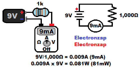
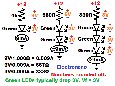
Current through a resistor is the voltage across it, divided by it’s resistance in ohms. 9V/1,000Ω = 0.009A, which is 9mA.
A current meter (ammeter) or multimeter that is set to measure current, has virtually no resistance. Current flows almost freely through the meter while current is being measured.
- Divide voltage.
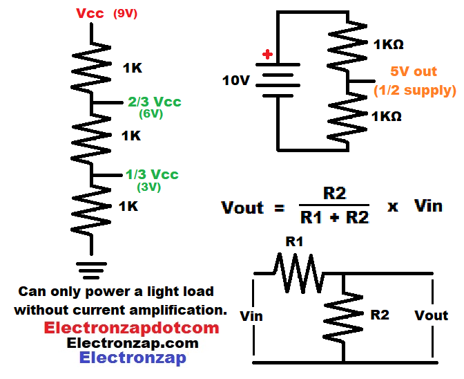
The voltage across series resistors gets divided up by each resistor based on their percentage of the total resistance.
The voltages can be used as signals for other circuitry that responds to that voltage.
You want the other circuitry to draw as little current from a signal as possible.
Having to provide current will throw off the voltage for most signals. Usually by a lot.
Two equal value series resistors will each have half of the total supply voltage across them. Whereas three equal value series resistors will have one third of the total supply voltage across them.
Pull up or down resistor:
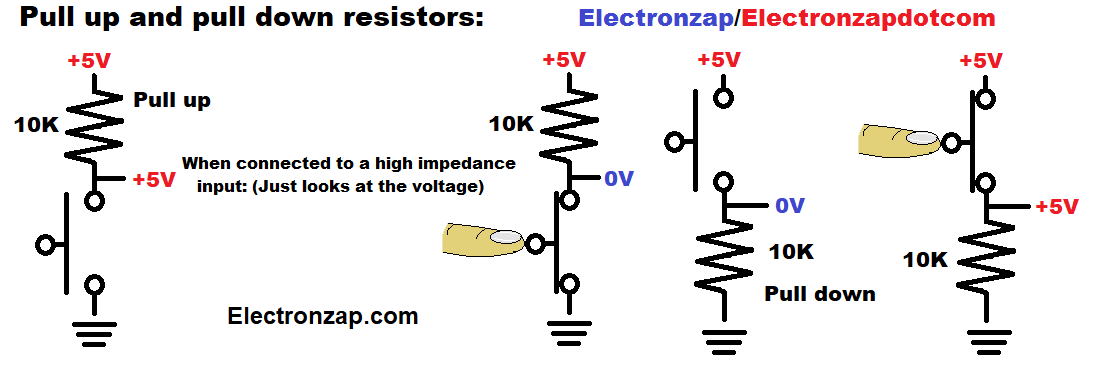
- Pull up/down resistor: A mechanical switch has pretty much zero resistance while closed (on), and almost infinite resistance while open (off).
- A series resistor will hold the voltage between them opposite of the voltage connected to the switch while it is open.
- Whereas a closed switch will make it so that the voltage between it and the resistor is the supply voltage connected to the switch.
Diode voltage drop:
- Diodes and some other components will drop a certain amount of voltage from a series resistor. After that, they often let current flow pretty much freely. The rest of the supply voltage (if it hasn’t all been dropped) ends up across the series resistance. That voltage across the series resistance is what ultimately sets the current that flows through all of the series components.
- Red and orange LEDs tend to drop about 2V.
- Blue, Green and White LEDs tend to drop about 3V.
- Diode voltage drops add up. 3 series green LEDs should drop about 9V total from a series current limiting resistor.
The current through a resistance in series with different types of diodes is covered in more detail when you study those topics.
Resistors are sometimes used for:
As you study circuits, you will occasionally come across these uses for resistors.
- Biasing. – A voltage divider can set a baseline input voltage/current to an input before a signal is applied. Commonly used with transistor amplifiers. No examples on this website as of writing this.
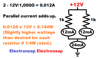
- Divide current. – Parallel resistors will each pass some of the total current. The total current is always higher than what flows through any individual parallel resistor. Their currents add up. Since there is always more current than any of the resistors alone, that is the equivalent of having less total resistance than any of the resistors would have have by themselves.
If you need 24mA from 12V, then using a single 500Ω 1/4W (0.25W) resistor will get too hot. 12V/500Ω = 0.024A (24mA). Multiplying the voltage across the resistor by the current in amps through it gives us the wattage. 12V x 0.024A = 0.288W. Quite a bit hotter than the maximum of 0.25W it is rated for.
2 parallel 1,000Ω resistors with 12V across them will each pass 12mA of current. 12V/1000Ω = 0.012A (12mA). But, since there are 2 parallel resistors, there will be a total of 0.012A times 2 resistors = 0.024A (24mA) where their paths come together (a node). Multiplying the current in amps across each of the resistors individual by the voltage across them, we get 12V x 0.012A =0.144W for each of them, independent of the other.
0.144W is a bit higher than the recommended 0.125W or less of a 1/4W (0.25W) maximum resistor, but it should be OK. Plus, there is almost always one or more series components that will help reduce the voltage and current the resistor has to deal with. So it is common to see 1k resistors in circuits powered by 12V because the other components drop some of the voltage, and therefore they won’t usually exceed 0.125W.
- Heating. – Usually heat from resistance is wasted energy and you want to avoid it as much as possible. You have to give components access to room temperature air, and sometimes add fan cooling, heat sinks, etc. if need be, to dissipate their rated value or more heat. A component without ventilation or that is covered (such as by dust) will be much more likely to overheat.
Electric heaters are one situation where we purposely use resistance to create desired heat.
Really nice looking resistor kit for those beginning studying electronics. Affiliate link ad.
Physical component:
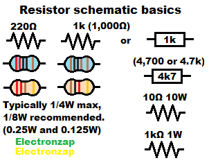
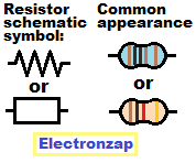
Through hole (wired) resistor components are usually close to cylindrical, but with a slightly narrowed middle. They also usually have colored bands that indicate their resistance value and tolerance.
Much higher wattage resistors are a lot larger than 1/4W resistors. They also usually look different, have their resistance value written on them, and they often also have their wattage written on them as well.
On schematic diagrams, the resistor component is usually indicated by jagged lines or less commonly as a rectangle. A recommended resistance value is usually written next to it if it is jagged lines, or inside of it if a rectangle is used as a schematic symbol.
- Ω – Omega symbol used to indicate the resistance in Ohms.
- Ohms – Unit of resistance.
Most resistors are rated for 1/4W (0.25W). However, it is still recommended to stay below 0.125W (1/8W).
Unless a schematic diagram indicates another value, or you calculate that a higher wattage component is needed, it should be OK to use a 1/4W resistor.
How to read schematic diagrams 01 resistor component basics for DIY electronics quarter watt 1W 10W: Click to watch directly on YouTube.
Knowing the value of a resistor:
- Value typically listed somewhere on packaging:
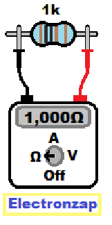
- Multimeter/ohmmeter measurement:
- Simply set the meter to measure resistance of a value more than you expect it to be if the meter is not auto ranging.
- Make sure the resistor is not part of a circuit (is open on one or both ends).
- Other components will alter the resistance results.
- If power is applied to the resistor, that could damage the meter.
- Then connect the meter probes to both sides of the resistor and read the value displayed
- Reading it’s color code (will be added later).
Current through a resistor:
Electric current flows through power sources, components and connectors in a manner similar to how water flows through pumps, pipes and appliances. Water and electricity don’t behave exactly the same of course. But, while studying basic electronics, you will be presented with water analogies that help you imagine current flow through components and the entire circuit.
Ohms law : I = V/R
Ohms law states that the current (I) in amps, through a resistance, is equal to the voltage (V) across the resistance in volts, divided by the resistance (R) in Ohms. I = V/R
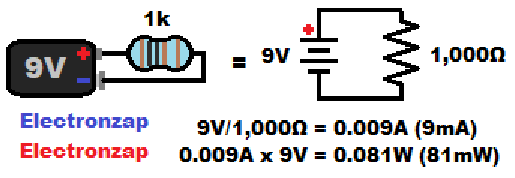
In the diagram shown here, we have 9 volts across a 1,000 ohm resistor. Giving us 9V/1,000 = 0.009A of current.
The current is calculated in amps while making the calculation. But, if the result is less than 1 amp of current, then the value is typically converted into milliamps. For example, 0.009A = 9mA. Which is pronounced as nine milliamps.
Without resistance, such as short circuiting a voltage source (battery), which should always be avoided, you will end up with the maximum current that the power source can provide. Many power sources can provide a dangerous amount of current.
Always avoid short circuits!
- For an ideal (impossibly perfect) voltage source: Any voltage divided by zero resistance equals an infinite amount of current. Ideal voltage sources are impossible to make, but manufacturers try to get as close as they can.
- Internal resistance (Battery): In the real world, there is always some opposition to current within a battery. Alkaline batteries have more internal resistance than lithium batteries. Therefore it is less dangerous to short circuit an alkaline battery than a lithium battery. Many lithium batteries have a protection board built into them to hopefully cut power if it is short circuited.
An alkaline 9 volt battery will likely only provide about 1 amp of current while it is short circuited. That means it has about 9V/1A = 9Ω of internal resistance.
Wattage/Power:
Most of the power (wattage) in electronics is in the form of heat. Unfortunately, too much heat is what destroys electronic components. Waste heat is unavoidable in electronics, but should be limited as much as possible.
You can’t see heat unless you are using thermal imaging, or something is hot enough that it emits light.
You will usually know (too late) that a component got too hot if it starts to glow, catches fire, or releases the magic blue smoke of a plastic covered component melting and emitting smoke.
Therefore, to avoid damage and possible injury, it is necessary to be able to calculate component wattage, and then to only use components that are rated at a higher wattage than those wattage calculations. By twice as much whenever possible.
Calculating wattage/power: P = VI
Power in electronics is voltage times current. That gives us the formula P = VI . For resistors, or any other kind of individual component, simply take the voltage (in volts) that is across the component and multiply it by the current (in amps) flowing though it. That will give you the power in watts that it needs to dissipate.
Topics to be added:
- Color code
- Variable resistor/Potentiometer/Trimmer potentiometer (trimpot).
- Information on this site is not guaranteed to be accurate. Always consult the manufacturer info/datasheet of parts you use. Research the proper safety precautions for everything you do.
- Electronzap is a participant in the Amazon Services LLC Associates Program, an affiliate advertising program designed to provide a means for sites to earn advertising fees by advertising and linking to amazon.com.