Table of Contents
Knowing how much voltage is across a resistor in a circuit is likely to be confusing when first studying electronics.
Just a power source across a resistor/resistive component:
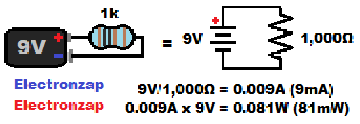
The simplest circuit is a voltage directly across a resistor or other resistive component. Incandescent light bulbs are one such resistive component.
A lone component has the full supply voltage across it when it is connected to a voltage source.
Current equals the power supply voltage, divided by the resistance. That is the basic Ohms law formula: I = V/R.
Diode (voltage) drops:
Less well explained to those starting to learn electronics, is the voltage drops that come with semiconductors and how they affect the voltage across resistors. It is important to understand voltage drops.
Generally speaking, diodes are semiconductors that generally conduct current in only one direction.
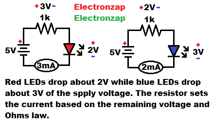
Other than conducting or not, they have almost no control over how much current flows through them once a certain voltage is across them. A resistor is commonly used in series with various diodes to limit the current through them to a safe level. When used as such, the resistor is referred to as a protective, or current limiting resistor.
The diode drops a certain amount of voltage from the resistor. The value of that voltage is it’s forward voltage in most cases. Zener diodes are different, they are used to drop their reverse voltage from series components.
After the voltage drop(s) are considered, then the current is set by the Ohms law formula I = V/R. Spoken as: “Current through the resistor (and series components) equals the voltage across the resistor divided by it’s resistance in Ohms”.
- Rectifier diode:
- Light emitting diode (LED):
- Zener diode:
- Other semiconductors with a “diode drop”:
Light Emitting Diode (LED) Forward Voltage Drops:
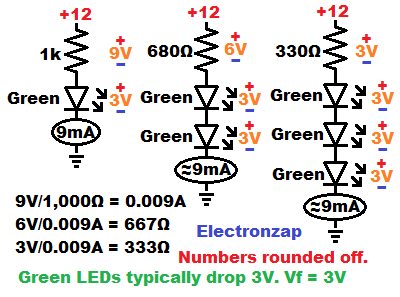
Indicator LEDs, the kind that are small and just produce enough light that you can tell they are on, tend to have a forward voltage of 2 to 3 volts.
In the diagram, I protect a single green LED, which usually has a forward voltage of 3V, with a 1,000Ω resistor.
That makes the math easy.
For every volt across the 1000Ω resistor, there will be 1 milliamp (1mA) of current through it. That will also be the current through series LEDs.
The green LED needs about 3 volts to conduct while forward biased, and it drops that voltage from any other series components. Therefore, with a 12V power supply, there will be 12V – 3V = 9V across the 1,000Ω resistor. 9V/1,000Ω = 0.009A or 9mA.
I also showed how to get the same amount of current (approximately) when adding more diodes in series. Each series LED drops some of the supply voltage from the resistor. therefore, a lower value resistor needs to be used, as more voltage is dropped from it.
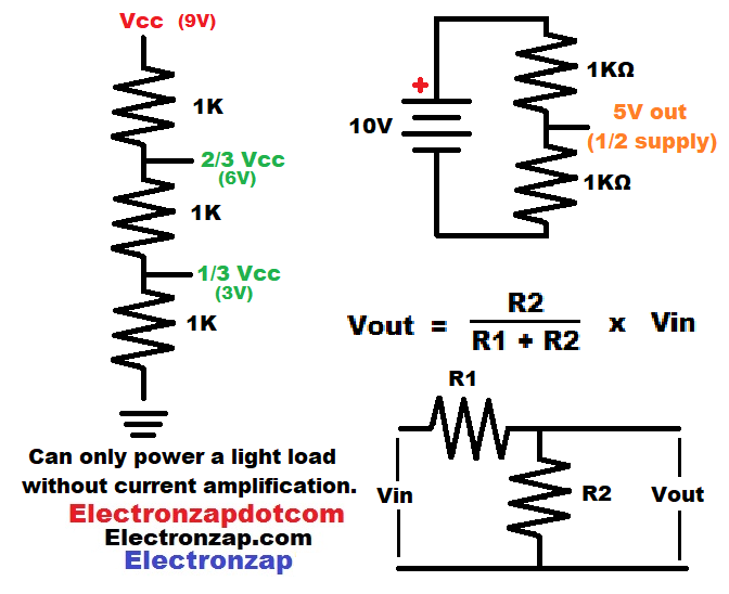
Resistor voltage divider:
Series resistances don’t drop voltage like diodes do. Instead, they divide up the voltage across each of them, based on each resistance’s percentage of the total resistance.
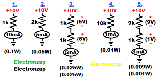
If 2 series resistors are equal value, then each will have half of the total voltage across them. In example #3, I illustrate how there will be 5 volts across each of 2 equal value series resistors with a total of 10V across them.
In example #5, I illustrate a resistor with 90% of the total resistance. It will have 90% of the total voltage across it. So 9 out of 10 volts.
Ohms law with series resistances:
Notice how in the examples above, the series resistances add up before setting the circuit current. For example 1,000Ω + 1,000Ω = 2,000Ω. Then, 10V/2,000Ω = 0.005A (5mA) circuit current.
When there are series resistors, the voltage across each of them will still match up with the ohms law formula V = IR. Voltage across the resistor equals the current through the resistor and the resistance of the resistor.
You can use that voltage as a signal (usually in relationship to ground).
An output signal is simply a voltage that the input of other circuitry can react to in some way.
If a voltage divider signal has to provide power (current), then the voltage will be thrown off. Therefore, the closer to zero current from a voltage divider signals, the better.
Some examples of circuitry that respond to weak signals.
- Voltage followers
- Op amp/comparator inputs
Other:
- Pull up/pull down resistors.
- RC time constant resistor voltages.
- Shorted capacitor (voltage across resistor).
- Charging capacitor voltage across resistor.
- Fully charged capacitor voltage across resistor.
- Parallel resistors.
To support this site, check out the following links:
- Become a Patron!
- Check out my YouTube videos! https://www.youtube.com/c/Electronzap/videos
- Products I used in my videos or otherwise think look like a good buy. As an Amazon associate, I earn from qualifying purchases. https://www.amazon.com/shop/electronzapdotcom
- Information on this site is not guaranteed to be accurate. Always consult the manufacturer info/datasheet of parts you use. Research the proper safety precautions for everything you do.
- Electronzap is a participant in the Amazon Services LLC Associates Program, an affiliate advertising program designed to provide a means for sites to earn advertising fees by advertising and linking to amazon.com.