Table of Contents
Diodes are 2 terminal components that have the basic electrical property of being polarized semiconductors.
Diode/LED basic properties:
Affiliate link ad.
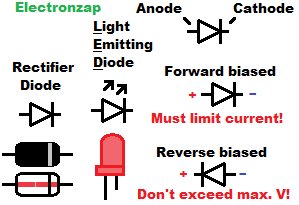
Basic Diode/LED rules.
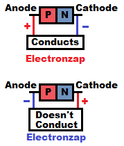
- Conducts easily while forward biased (Anode more positive than Cathode).
- Blocks current while reverse biased (Anode more negative than Cathode).
- There are number of voltages to be aware of when dealing with diodes/LEDs. They vary greatly between types of diodes/LEDs, and part number.
Light Emitting Diodes (LEDs) behave electrically like other diodes, but while forward biased, they drop more voltage and can’t handle much current. Usually 20mA or less is recommended for most LEDs.
The LED emits light, which is nice for demonstration circuits. You can’t see electricity directly, but you can easy notice it producing light .
LEDs don’t block near as much voltage while reverse biased as rectifier diodes can. Based on earlier testing I did, somewhere around 10-12V destroyed my reverse biased LEDs. While forward biased, only the forward voltage (usually 2-3V) will build up across the LED, and then all of the rest of the voltage will be passed on to the other series component(s).
All diodes need series protection. They don’t limit current by themselves, once there is enough voltage to get them to conduct.
The 1N4001 rectifier diode is commonly included with electronic kits. It has a forward voltage of 0.6V to 0.7V, and a rated maximum reverse voltage of 50V.
Although we usually imagine conventional current while we are analyzing the flow of charges in a circuit, studying how semiconductors operate requires the understanding of how electrons flow.
Nice assortments of semiconductors (lots of diodes but no LEDs). Amazon affiliate link ad.
Illustrative diagram below is based on electron flow. Electrons move from negative to positive. Unfortunately early misunderstandings of electric current gave us a circuit analysis system where we imagine current as flowing from positive to negative. One amp of positive (conventional) current flowing in one direction means exactly the same thing as one amp of electrons flowing in the opposite direction.
Important diode/LED topics:
- N type material (cathode) versus P type material (Anode)
- Forward biased – Forward Voltage
- Reverse biased – Peak Inverse Voltage (PIV)
- Rectifier diode – Schottky diode
- Light Emitting Diode (LED)
- Zener diode
N type (Cathode) versus P type (Anode) material:
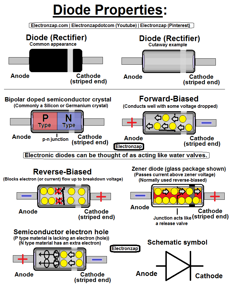
Diodes are made mostly of a semiconductor atom, typically silicon, which has 4 outermost (valence) electrons. Pure silicon electrons connect together ( form a matrix) pretty well and are relatively hard to move. It has a fair amount of resistance in it’s pure form.
- N type material: Some amount of 5 valence electron material (dopant) is added to the 4 valence electron semiconductor material. The extra valence electron can be removed relatively easily.
- This side of the diode component is called the cathode.
- P type material: Some amount of 3 valence electron material (dopant) is added to the 4 valence electron semiconductor material. The extra space for an electron makes it relatively easy to move an electron through that “hole” in the electron matrix.
- This side of the diode component is called the Anode.
Forward Biased – Forward Voltage:
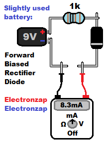
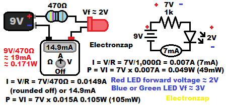
While forward biased, it still takes some voltage before the diode will conduct. That voltage is ultimately lost to the rest of the series components in relationship to the power supply voltage. This is due to the forward voltage staying across the diode, while the rest of the supply voltage is passed along to it’s series components.
9V with a 0.7V rectifier drop would give us about 9V-0.7V = 8.3V across a current limiting resistor in series with it. If that resistor is 1,000Ω (same as 1k), then we will have 8.3V/1,000Ω = 0.0083A (8.3mA) of current through the entire series circuit.
::NOTE:: You can measure those voltages with a multimeter, and even use them as a signal for other circuitry if desired.
In the diagram, I show the connections needed to measure current. The circuit must be opened, and the meter must be connected in series with the other components. The meter must be set to a setting that can measure more current than will be measured, or the meter may be damaged (blown fuse most likely). Measuring current does not limit the current while measuring it.
Typical diode forward voltages (Vf)
- Silicon based diode – approx. 0.7V (0.6V at low current)
- LED –
- Approx. 2V for red, orange, etc. colors.
- Approx. 3V for blue, green, etc. colors.
- Germanium based/Schottky diode.
- approx. 0.3V
Forward voltage is often abbreviated by the symbol Vf.
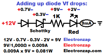
Forward voltages can be added up.
The diagram above shows a red (Vf of 2V) LED, combined with a silicon (Vf of 0.7V) rectifier diode, and a Schottky (Vf of 0.3V) diode in series. That’s how you could drop 3V of the supply voltage from reaching the current setting resistor, if that were a goal you had. I used a 12V power supply in this example.
12V – 3V = 9V across a 1,000Ω (1K) resistor results in 9V/1,000Ω = 0.009A (9mA) of current through the circuit.
Reverse Biased – Peak Inverse Voltage/Peak Reverse Voltage:
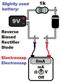
The diode is reverse biased (RB) when the Anode is more negative than the Cathode. Diodes have the basic property of not conducting current while reverse biased (unless specially made to do so). But of course they do have limitations to be aware of.
-
- Peak Inverse Voltage (Peak Reverse Voltage): The voltage at which a reverse biased diode is expected to “breakdown”. That’s when current can be expected to start flowing even though the diode is reverse biased. The diode may be destroyed if it is not specially made to conduct current while reverse biased.
- Zener diodes are a commonly used type of diode that is specifically made to conduct current while RB.
- Rectifier diodes usually have the highest PIV/PRV values. You need to check the datasheet for the value of a particular diode (look up it’s part number) to know it’s exact value.
- The commonly found 1N4001 has a 50V Maximum Repetitive Peak Reverse Voltage (VRRM) according to the Vishay manufacturer’s datasheet. I found the datasheet by doing a simple google search.
- The datasheet also says that the 1N4002 has a VRRM of 100V. An example of a different diode’s rated breakdown voltage.
- Alternating current has a voltage that goes up and down, in both directions. So if you are told that the voltage of AC is 35VRMS (Root Mean Square), then that means that the voltage is lower than 35 volts for part of the time, and it is above 35V the other part of the time. It probably gets to about 50V at it’s peak because according to the Vishay datasheet, the 1N4001 maximum VRMS is 35V.
- Another example is that the maximum VRMS for the 1N4002 is 70V. You can’t exceed the PIV for any period of time. So, you must keep the peak voltage in mind whenever you are looking at a Root Mean Square voltage that will be applied to a diode.
- LEDs don’t seem to have a very high PIV at all. During some earlier testing, I burned some out instantly somewhere between 10 and 12V while RB. That happened even though it had a protective resistor limiting current well below 20mA. I don’t think I have ever found manufacturer ratings for the PIV of RB LEDs. They aren’t meant to rectify voltage/current, so that is no surprise.
- Peak Inverse Voltage (Peak Reverse Voltage): The voltage at which a reverse biased diode is expected to “breakdown”. That’s when current can be expected to start flowing even though the diode is reverse biased. The diode may be destroyed if it is not specially made to conduct current while reverse biased.
Rectifier Diode – Schottky Diode:
- Rectifier diodes are intended for rectification. That is taking an AC voltage source, and making it so that the current flows in one direction only. They have a somewhat low forward voltage (usually 0.6V – 0.7V), and a high to very high reverse voltage. Usually anywhere from 50V to thousands of volts, depending on the specific rectifier diode being used. Some are lower though! Always consult the datasheet for the particular part number you have.
- Schottky diodes have a lower forward voltage than the rectifier diode. Usually somewhere around 0.3V. That is helpful if losing 0.7V is a little bit too much to lose.
Compared to silicon rectifier diodes, Schottky diodes usually don’t have as high of a reverse biased breakdown voltage, and will also leak more current while reverse biased.
Light Emitting Diodes (LEDs):
LEDs are diodes made specifically to emit light when they are conducting current while forward biased.
- Indicator LEDs are mostly intended to only light up enough that you notice that they are lit up. They aren’t used for lighting an area. However, some can get bright enough that they are hard to look at directly and may light up an area a bit.
- Commonly available indicator LEDs usually have a recommended forward current of no more than 20mA.
- Protective resistors are typically used to limit the current flowing through LEDs. Any other way that limits current through the LED can be used instead.
Zener diode:
Zener diodes are specially made to conduct while reverse biased. They are made to do so at a specific voltage for the individual diode. They come in many values.
Although the zener diode component is made to conduct at a specific voltage, the actual voltage will still vary a small amount based on how much current is flowing through it.
- The voltage that a particular zener diode is made to conduct while it is reverse biased is called it’s zener voltage.
- Reference voltage:
- When the zener diode’s Anode is connected to negative ground, and current is passed through it, then it builds up it’s zener voltage across it.
- That voltage gives a reference voltage to other circuitry, which will not change much, even as the supply voltage changes. The current can be limited by a resistor, or set by a current source.
- A steady current through the zener diode will hold a steady voltage across it.
- The zener voltage is just a signal. It should provide almost no current. Any current it needs to supply, will likely drop the voltage.
This page is still being updated!
- Become a Patron!
- My YouTube videos! https://www.youtube.com/c/Electronzap/videos
- Affiliate link products https://www.amazon.com/shop/electronzapdotcom
- Information on this site is not guaranteed to be accurate. Always consult the manufacturer info/datasheet of parts you use. Research the proper safety precautions for everything you do.
- Electronzap is a participant in the Amazon Services LLC Associates Program, an affiliate advertising program designed to provide a means for sites to earn advertising fees by advertising and linking to amazon.com.