Table of Contents
Bipolar Junction Transistors (BJTs) have three terminals called Collector (C), Base (B), and Emitter (E).
- Collector
- Base
- Emitter
A small amount of current flowing from Base to Emitter allows a large amount of current to flow from Collector to Emitter.
No base to emitter current, means no collector to emitter current.
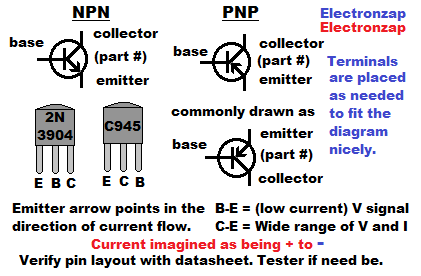
There are 2 types of bipolar junction transistors, NPN and PNP. They have opposite polarities (the direction that current flows), but otherwise operate the same way.
- NPN: 2 N type material areas (terminals) with a p type material area (terminal) between them.
- PNP: 2 P type material areas (terminals) with a N type material area (terminal) between them.
Notice how the 2N3904 physical component has a different pin layout (location of collector, base, and emitter) than the C945 even though they are both in the TO-92 package (look the same). Always check the datasheet of the transistor you are using for the correct pin layout. TO-92 package is the most common appearance of through hole transistors and other types of 3 terminal semiconductors.
Nice assortments of semiconductors that I use in my videos. Includes 2N3904 NPN BJTs and 2N3906 PNP BJTs. Amazon affiliate link ad.
Base Current (Ib)
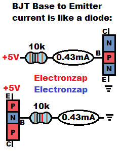
Base to Emitter acts like a diode. The BJT doesn’t control the amount of current that flows from B-E, other than having an approx. 0.6V forward voltage for almost all BJTs. Remember that a diode is forward biased when the Anode is more positive than the Cathode. Anode is P type material, while Cathode is N type material.
When a signal (voltage and as little current as possible) is applied to the base, then the amount of current that flows from the B-E determines how much current will be allowed to flow from C-E. That amount is based on the transistor’s gain.
A 10k resistor base resistor is used in the diagram to limit current through base to emitter.
- 5V – 0.7V diode drop = 4.3V across current setting resistor at the base.
- 4.3V/10,000Ω = 0.00043A , which is the same as 0.43mA of current through B-E.
- Conventional current (imagined as flowing from more positive to negative, +5V to ground in these examples), flows through PNP BJTs in the opposite direction of how it flows through NPN BJTs.
- Electrons actually flow from negative to positive, but were unknown when scientists started studying electricity. They assumed that a positive fluid like force flowed from positive to negative, and we still imagine current flow in that was while analyzing circuits.
Collector current (Ic) and gain:
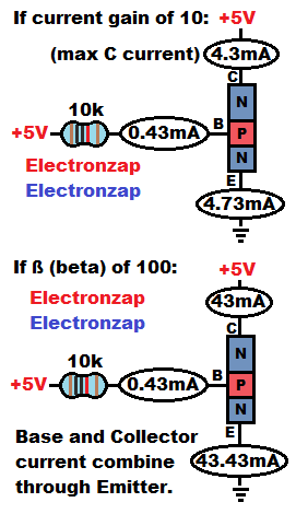
For every charge that flows through base to emitter, usually in the microamp range, it allows many times more charges to be allowed to flow from collector to emitter. This is known as gain.
- Gain, hFE, and beta (ß) are 3 commonly used ways to refer to the multiple amount of Collector current flow in relationship to the Base current flow of a bipolar junction transistor.
If a NPN BJT has a gain of 100, and you put 1mA of current through it’s B-E, then it will allow 100mA of current to flow from collector to emitter.
Lots of BJTs have a gain that may vary from around 200 to 300. But always consult their datasheets for the best estimates instead of assuming it’s gain.
It is also important to know that the gain for a particular bipolar junction transistor also varies with the conditions it is being subjected to. You just want to make sure that the transistor that you want to use will always have a lot more gain than you will need. Other circuitry will ultimately be what set the current. You will learn about that other circuitry while you studying BJT circuits.
This is probably confusing for most people who are starting to learn about it. But, it will make a lot more sense as you study simple BJT circuits. Especially if you build the circuits on a breadboard and take multimeter measurements.
Topics that will be added later:
Important topics, most that I will cover in more detail on this page later.
BJT collector to emitter conduction:
- Cutoff region – No conduction,
- Active region – Some conduction, but not full.
- Saturation – Fully conducts, load is what limits the current.
Common BJT circuit fragments:
Keep in mind, that there are a lot of transistor circuit fragments that you might not build yourself, but will encounter in one way or another. Therefore, by understanding them, you will better understand their limitations, and/or modify other circuits.
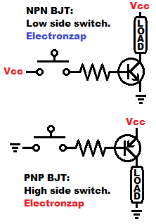
Basic schematic diagram of bipolar junction transistor switch circuits.
I’ll probably devote a page to each of the circuits below, instead of making this page a lot longer.
- Switch: C-E drops almost no voltage while on, drops all voltage when off. BJT wired as a switch
- Current source/sink: C-E drops undesired supply voltage as needed to maintain a certain voltage across a resistor.
- Emitter/Voltage follower. C-E drops base voltage with a difference of approx. 0.6V
- Inverted amplifier/switch. C-E takes away all voltage when on, and takes away no voltage when off.
- Schmitt trigger.
- Current mirror.
- Differential amplifier.
- Rubber diode – Adjustable zener.
This is a new page that will be updated soon!
To support this site, check out the following links:
- Become a Patron!
- Check out my YouTube videos! https://www.youtube.com/c/Electronzap/videos
- Products I used in my videos or otherwise think look like a good buy. As an Amazon associate, I earn from qualifying purchases. https://www.amazon.com/shop/electronzapdotcom
- Information on this site is not guaranteed to be accurate. Always consult the manufacturer info/datasheet of parts you use. Research the proper safety precautions for everything you do.
- Electronzap is a participant in the Amazon Services LLC Associates Program, an affiliate advertising program designed to provide a means for sites to earn advertising fees by advertising and linking to amazon.com.