Table of Contents
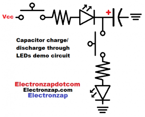
Current flows from Vcc to ground when the top switch of the diagram is closed. A protective resistor, LED and capacitor are in series with the switch. Therefore the LED lights up and the capacitor charges until it is the LED’s voltage drop less than Vcc.
As the capacitor charges closer to the Vcc voltage, the resistor lets less current flow, and the LED gets less bright. There is less and less voltage difference between Vcc and capacitor voltage.
The lower switch heads from the positive side of the capacitor to ground. When the switch is closed while the capacitor is charged, the capacitor discharges through the resistor and LED until it reaches the LED voltage drop.
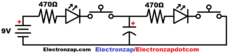
Below: We start with a discharged capacitor. Both switches are open, so no current flows.
Closing the switch on the high side (Vcc/positive side of battery etc.) lets current flow from the supply and into the capacitor. That current also flows through the current limiting resistor and LED, lighting up the LED. The LED needs a certain amount of voltage (forward voltage) to conduct current while forward bias. Therefore, the capacitor will stop charging when it is an LED voltage drop below the supply voltage.
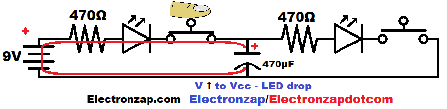
After the capacitor is charged, and the high side switch is released, then the capacitor will hold that charge and the voltage across it.
Closing the low side (ground/negative) switch allows the capacitor to discharge through the other current limiting resistor and LED. At this time, the capacitor is the power source for the resistor and LED. It is using the stored charge that it obtained from the battery as power.
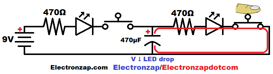
Once the capacitor voltage drops to the LED forward voltage, current will stop flowing.
Video:
To support this site, check out the following links:
- Become a Patron!
- Check out my YouTube videos! https://www.youtube.com/c/Electronzap/videos
- Products I used in my videos or otherwise think look like a good buy. As an Amazon associate, I earn from qualifying purchases. https://www.amazon.com/shop/electronzapdotcom
- Information on this site is not guaranteed to be accurate. Always consult the manufacturer info/datasheet of parts you use. Research the proper safety precautions for everything you do.
- Electronzap is a participant in the Amazon Services LLC Associates Program, an affiliate advertising program designed to provide a means for sites to earn advertising fees by advertising and linking to amazon.com.