Table of Contents
Non inverting op amp comparator circuits have an output that looks more like the signal voltage than the reference voltage. Comparing which one is higher or lower, and then outputting as close to the rail voltage that it can, in the direction of the signal voltage, compared to the reference voltage.
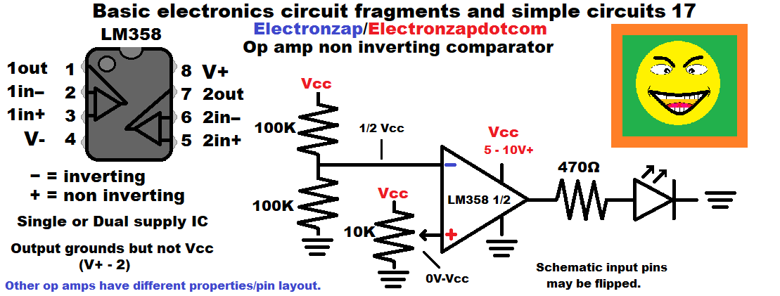
- A fixed voltage is applied to the inverting (-) input. In the diagram, it is half of whatever the supply voltage (Vcc) is (in relationship to ground). The – input voltage only changes if the supply voltage changes.
- The adjustable voltage (signal) is applied to the non inverting input (+).
- A higher + input voltage than the – input results in a high output.
- Lower + input voltage than the – input results in a low output.
- LM358 output
- Is pretty much 0V ground when low.
- About 1.5V shy of the positive supply when high.
Video:
To support this site, check out the following links:
Art of electronics is easily my favorite learning electronics book. It helps to already be familiar with basic electronics while studying it. It inspires many of my demonstration circuits. An affiliate link ad that supports this site.
- Become a Patron!
- Check out my YouTube videos! https://www.youtube.com/c/Electronzap/videos
- Products I used in my videos or otherwise think look like a good buy. As an Amazon associate, I earn from qualifying purchases. https://www.amazon.com/shop/electronzapdotcom
- Information on this site is not guaranteed to be accurate. Always consult the manufacturer info/datasheet of parts you use. Research the proper safety precautions for everything you do.
- Electronzap is a participant in the Amazon Services LLC Associates Program, an affiliate advertising program designed to provide a means for sites to earn advertising fees by advertising and linking to amazon.com.