Table of Contents
Astable mode 555 timer is when the 555 timer integrated circuit output keeps alternating between high and low.
That means that the output keeps changing between 0V, and as close to the supply voltage as the output can go. This happens as long as power is applied. It never stops. It has no stable state of either high or low. That’s why it is referred to as astable.
Basic circuit example:
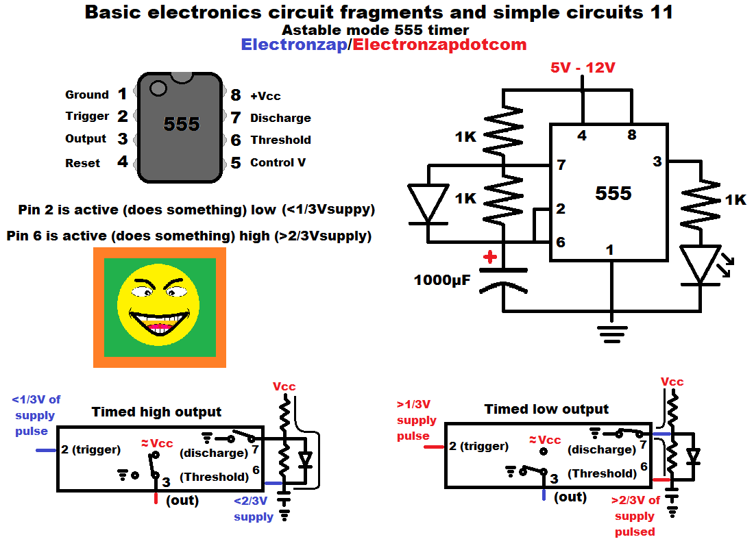
- The timing capacitor charges from the positive supply voltage through one resistor and a diode when wired as above. The output is high while it does so. Therefore the LED in this circuit is lit (on). Usually the output voltage is about 1.5V less than the positive supply voltage while it is high.
- When pin 6 (threshold) senses that the capacitor has charged to 2/3 or more supply voltage, then the output switches to low (connects to ground). That turns off the LED in this circuit. Pin 7 (discharge) also goes from being off (no conduction) to low. Being low means that they both connect to 0V ground really well. The capacitor starts discharging through the resistor that is between the connected together pins 6 (threshold) and 2 (trigger), and pin 7 (discharge). Any current through the + supply voltage and pin 7 resistor goes right to ground at this time and does not affect the capacitor discharge time at all.
- When pin 2 (trigger) senses that the capacitor has discharged to 1/3 or less of the supply voltage, then the output goes high. That turns the LED back on, and pin 7 (discharge) basically turns off. It stops conducting current through it, and the capacitor starts charging again.
High side load and good voltage measurement points:
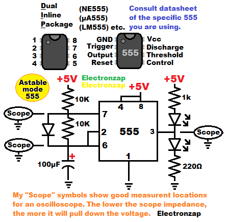
This diagram has and LED and protective resistor on the high side of the output, as well as the low side.
The high side (connected to +5V) LED lights up when the output is low.
The low side (connected to ground) LED lights up when the output is high.
I added “scope” bubbles to show good spots to take oscilloscope measurements. That way you can see the voltage changing in real time.
You touch the measurement probe/red alligator clip to where the bubble is pointing to and attach the ground/black clip to 0V ground.
Video:
To support this site, check out the following links:
- Become a Patron!
- Check out my YouTube videos! https://www.youtube.com/c/Electronzap/videos
- Products I used in my videos or otherwise think look like a good buy. As an Amazon associate, I earn from qualifying purchases. https://www.amazon.com/shop/electronzapdotcom
- Information on this site is not guaranteed to be accurate. Always consult the manufacturer info/datasheet of parts you use. Research the proper safety precautions for everything you do.
- Electronzap is a participant in the Amazon Services LLC Associates Program, an affiliate advertising program designed to provide a means for sites to earn advertising fees by advertising and linking to amazon.com.